Apollo Computing Laboratories (P) LtdInnovation is our Tradition
+91-40- 27141522, 27141533
RF & Microwave Products
The following are the some of Products designed & developed by ACL. All our products have been made use of in the Defense & Aerospace Sector. These Products can be customized with specific requirements by profile, interface as well as software .
ACL has been recognized as a MIL grade quality production unit through the order placement for Quantity production of the Missile Interface Unit, On-board computer systems designed, developed & qualified by ACL for the IGMDP Program.
There are many other DRDO & Aerospace projects being done & in the anvil, which are enabling wider involvement’s of ACL in the National programs.
206.5 MHz PROFILER

This is a Phased array radar under development for wind profiling studies in the Stratosphere and Troposphere atmospheric layers.The radar operates in the 200 MHz band with a carrier frequency of 206.5 MHz.The radar provides vertical and horizontal profiles of wind velocity upto altitudes of 0.5 to 20 Kms, or higher depending upon the atmospheric conditions. System supports horizontal velocities of 1m/sec to 70 m/sec and vertical velocities of 1m/sec to 30m/sec. Three dimensional wind data is provided on a continuous basis which is used for studying the development of wind shears in almost real time.
The system is built around a large array of 588 Yagi antennas arranged in a circular partten driven by an array of 588 Transmit- receive modules generating a pulse power of 400 watts peak/module. The pulse waveforms are generated by a coherent signal generator based on DDS modules. The signal processing is implemented using Pulse doppler radar signal processing algorithms. The system is provided with a eassy to use GUI and recording capability.
ST-Radar -System Level Specifications:
Operating Frequency : Around 180-225MHz (Depending upon allocation by WPC)
BandWidth : < 5MHz
Peak Power Aperture Product: 1*10P8 Wm2
Height coverage : 0.5 to 20 Km (nominal)
Height resolution: 50m to 150m upto 16 km,300m from 16 to 20 km
Horizontal Wind velocity : 1 m/s to 70 m/s
Vertical Wind velocity : 1 m/s to 30 m/s
Velocity resolution : 0.1 m/s to 2 m/s depending on the magnitude
Accuracy in Horizontal comp. wind : 1 m/s (typical)
Accuracy in Vertical comp. wind : 0.1 m/s (typical)
Time resolution : 10 min for full profile (typical)
Angle resolution : 3° (typical)
SubSystem Specifications:
Antenna:
Aperture : 32 m dia
Type : Active Phased array with 3 element Yagi antenna
Gain : 34 dB (typical)
Beam width : 3° (typical)
No. of beams : Programmable in azimuth abd elevation
Scan angles : 15° (typical) from zenith in steps of 1°
Transmitter:
Type : Coherent, T/R module based
Peak power : 230Kw
No. of T/R modules : ~576
Peak power o/p of T/R module : ~400 W
PRF : 250 Hz - 8KHz programmable
Pulse width : 0.5µsec to 64µsec-uncoded, 16µsec to 64µsec-coded
Coding : Complementary coding
Receiver:
Type : Coherent
Noise Figure of LNA : < 2 dB
System Noise Temperature : 695° K at LNA I/P
Dynamic range : 70 dB(typical)
IF : 30MHz
Data Acquisition & Signal processing:
Type : Base band signal generation of I & Q signals with digital Rx at IF Nyquist/sub-Nyquist sampling and programmable decimation.
Data resolution : 14 bit.
Sampling rate : 65 MS/sec (typical).
No. of range gates : Programmable upto 512.
No. of coherent integrations : Programmable upto 1024.
Spectral estimation : FFT based (Real time).
No. of points for spectral estimation : Programmable upto 512.
No. of spectral Integrations : 1 to 10 (selectable).
Moments, u, v, w : In near real time.
Type of signal processor : Dedicated processor.
System computer : PC based RT Linux/Vx works.
Display : High resolution LCD (19" monitor).
Data archival : DLT/ CD/ DVD.
Hard copy : Color laser jet printer.
53MHz/1KWatt TR Module
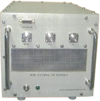
This Transmit-Receive Module (TRM) is developed for a wind profiler radar for operation in HF Band.
It is operating at a centre frequency of 53MHz with a band width of 5MHz. It is designed for the Pulsed application (0.5us to 200us) and the maximum duty ratio is 10%. The TRM receives a -5dBm pulse as transmit input and generates 1KW pulsed output. The TRM has phase and amplitude programming with a 6 bit phase shifter and 4 bit digital attenuator in both Tx and Rx paths.
It provides a gain of 28dB in the Rx path and Noise figure of < 4dB. Features an excellent isolation of 60dB from Tx to Rx. Input Over drive,High VSWR and thermal interlocks are provided for TRM safety.
Operating Frquency : 53.5 MHz
Input Power : 0dBm(max).
BandWidth : >3.45MHz
Peak Output Power : 1.0 kW ±1dB
Hormonic Level : < 40dB
Duty Ratio : upto 10%
Mode of Operation : Pulsed
Pulse Width : 0.5 - 200μS
Rise /Fall Time Width : < 150 ns
Impedance : 50 Ohm
Protection : Thermal,VSWR
RF Connectors for TX,RX,ANT Ports : N(Female)
TX-RX Isolation(at high speed): >50 dB(min)
Power Supply : 230v AC,50Hz,1-ø
AC Connector : 3 Pin Socket
Interface Connector : D-Type,Multi-Pin
Operating Temperture : 0°C to 55°C
Humidity : 95% at 40°C
150MHz/1KWatt TR Module
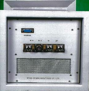
This is a Transmit- Receive Module developed for lower atmospheric wind profiler radars.The TR Module operates peak power of 1Kwatt and handle upto 10% duty cycle.It is suitable for feeding any phased array, antenna array in corporate feed networks. The TR module is packaged in a size of 500x245x222mm and weight is less than 12kg.The TR module is rated for operation up to +55°C with forced air cooling.
Analog Outputs :
Operating Frquency : 150 MHz
Input Power : 0dBm(max).
BandWidth : >3.45MHz
Peak Output Power : 1.0 kW ±1dB
Hormonic Level : < 40dB
Duty Ratio : upto 10%
Mode of Operation : Pulsed
Pulse Width : 0.5 - 200μS
Rise /Fall Time Width : < 150 ns
Impedance : 50 Ohm
Protection : Thermal,VSWR
RF Connectors for TX,RX,ANT Ports : N(Female)
TX-RX Isolation(at high speed): >50 dB(min)
Power Supply : 230v AC,50Hz,1-ø
AC Connector : 3 Pin Socket
Interface Connector : D-Type,Multi-Pin
Operating Temperture : 0°C to 55°C
Humidity : 95% at 40°C
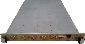
206.5MHz/4KWatt TR Module
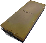
This Transmit-Receive Module (TRM) is developed for a VHF wind profiler radar, ST Radar, M/S ARIES, Nainital.
It is operating at a centre frequency of 206.5MHz with a band width of 5MHz. It is designed for the Pulsed application (0.5us to 64us) and the maximum duty ratio is 15%. The TRM receives a -4dBm pulse as transmit input and generates 400W pulsed output. The TRM has phase and amplitude programming with a 6 bit phase shifter and 6 bit digital attenuator in both Tx and Rx paths.
It provides a gain of 28dB in the Rx path and Noise figure of < 4dB. Features an excellent isolation of 70dB from Tx to Rx.
The module is equipped with a CAN Interface for external connectivity. It receives a differential trigger signal IPP to generate the internal timing signals. High VSWR and thermal interlocks are provided for TRM safety. The Auto calibration and phase calculation for beam formation are special features of the TRM.
Analog Outputs :
Frequency : 206.5 MHz
BandWidth : 5MHz
Phase Control:Digital 5.625°/Step,360°Total range.
Gain Control : Digital 0.5dB Step,Total Range:31.5 dB
Gain error between modules :0.5 dB
Phase error between modules : 6°
Operating Mode : Remotely Controllable by RC
Protection from Lightning : Provided at the antenna port
RF peak power O/P : 400W, Minimum at ambient Temp.
RF Average power : 52W
Input RF drive power : -4dBm ± 1.0 dB(pulsed)
Input modulation : Pulse modulation
Pulse width : 0.5-64µsec uncoded 16-64µsec coded with baud width 0.5 & 1.0µsec
PRF: 250Hz to 8KHz
Duty cycle : 13% max
Rise time & Fall time : < 175 nsec
Noise Figure of the Rx path : ≤4.0dB
Receive path Gain : 24dB ±2 dB
Rx path 1dB compression point : -2 dBm
Status : a) Excess temperature, b) Excess VSWR, c) RF output power
Inter lock : Gate to SSPA disabled on failure of OVT flag or VSWR flag or both
External Interface : CAN 2.0B
Monitoring : CAN 2.0B
DC Power Required : 32V@4.0Amps, 5V@1Amp
Efficiency : 50% (typical)
RF IN, RF Monitoring & Antenna port connectors : N(F), SMA(F) & N(F) respectively
Power Supply : MS Circular
Control signals : D sub/RJ 45 connector
Cooling : Natural Cooling
Recovery time : < 4µsec (Typical)
Operating temperature : Temp: -5 to +40°C
TR Module size : 484mm x 200mm x 87mm
450MHz/1KWatt TR Module
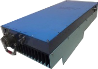
This Transmit-Receive Module (TRM) is developed for a wind profiler radar for operation in UHF band.
It is operating at a centre frequency of 450MHz with a band width of 5MHz. It is designed for the Pulsed application (0.5us to 64us) and the maximum duty ratio is 15%. The TRM receives a 0 dBm pulse as transmit input and generates 1KW pulsed output. It is suitable for Phased Array Radar with corporate feed network. The TRM has amplitude programming with 6 bit digital attenuator in both Tx and Rx paths.
It provides a gain of 28dB in the Rx path and Noise figure of < 4dB. Features an excellent isolation of 60dB from Tx to Rx. High VSWR and thermal interlocks are provided for TRM safety.
Analog Outputs :
Frequency : 450MHz
BandWidth : 5MHz
Gain error between modules : 0.5dB
Phase error between modules : 6º
RF peak power output : 1000W,±0.5dB.
Input RF drive power : 0dBm,±1dB.
Input modulation :Pulsed modulation
Pluse width :1-64µsec uncoded , 16-64µsec coded
Rise time & fal time :< 250nsec
Receive path Gain :30dB,±2dB(nominal)
Noise figure of Rx path :< 5.0dB
Status : a).Excess Temperature b).Excess VSWR c).RF power output
Inter locks : Excess Temperature Excess VSWR
Dynamic Range : -70dB
Efficiency : 40% Typical
RF IN,RF Mom. & Antenna Connectors : N(F)
Power Supply & Control Connectors : MS Circular(10 Pin)
DC power required : 50V@10A,24V@2A,5V@2A
Cooling : Forced Air
Operating temperature : -10 to +55ºC
Storage temperature : -20 to +70ºC
TR Module size : 491mm x 200mm x 135mm
Signal Distribution Unit
The unit carries out the function of distributing RF signals receieved through three antenna inputs to any of the two outputs . The two antenna inputs cover the frequency range of 20 to 500 MHz and 500 to 2000 MHz. The RF signals received by the two antennas are processed , combined and distributed to two different receivers operating over 20 to 2000 MHz, for the purpose of monitoring and analysis. The unit is built around LNAs, low pass and band pass filters and combiners. The SDU has built in BITE source . In BITE-Tx mode amplitude modulated test signal at spot frequency is is is available for radiation by the selected antenna. In BITE-Rx mode ampitude modulated test signal at a spot frequency is fed through SDU chain to the designated receiving system.
Input Specifications :
| Input One : |
|
||||||
| Input Two: |
|
||||||
| Input Three : |
|
Output Specifications :
| Output One : |
|
||||||||||||||||
| Output Two: |
|
Antenna Switching Unit
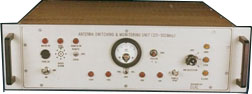
The antenna switching unit is designed to facilitate switching of any one the antennas from among a cluster of antennas into a common output. The switching circuit caters for a frequency range up to 2000 MHz. The firm has capability to design any switching matrix over a wide range of frequency bands. The switching unit features low insertion loss, load VSWR protection, isolation better than 60 dBc and is protected against hot switching.
Frequency Coverage : a) 20-100 MHz b) 100-500MHz
Input/Output Impedance : 50 Ohms
Power Handling : 1.5 KW
Switching Time : ≤ 40 m Sec
Insertion Loss : ≤0.5 dB
Inter port Isolation : ≥ 60 dB
Mode of Operation : LOCAL / REMOTE
Mechanical : 4U High & Depth 500 mm (Max) (SS19"Rack Mountable)
PROGRAMMABLE RF Source 1.5MHz To 2000MHz-2-50 Watts
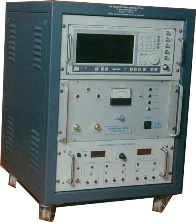
Programmable RF source is designed for operation in the band of 1.5 to 2000 MHz. The source is meant for testing of communication systems. The unit can be remotely programmed for bands, RF power and modulation types. The unit is suitable for different applications like Communication EW receiver testing using complex signal generation, generation of Jamming signals etc, The unit features high efficiency, Class AB operation, thermal and VSWR protection.
Frequency : 1.5MHz to 2000MHz in selected bands
Input : 0 dBm ± 1db
Output power : 2-50 Watts
Harmonics : ≤ -20 dbc
Spurious : ≤ -60 dbc
Protections : High Load VSWR, Input over drive, Thermal over load
Operation : Local / Remote
Supply Voltage : 230V AC
Operating Temperature : -10°c to +55°c
Support
The products will be under warranty for a period of 12 months from the date of installation.
In this period all the products supplied will be covered under comprehensive warranty inclusive of all the parts of the system / equipment against any manufacturing / design defects.